Lab Exercise - Interfering Processes
Several physical processes interfere with the efficiency of liquid scintillation counting- chemiluminescence, photoluminescence, and other general processes which is generally referred to as background.
Background
The numerous processes grouped under the heading of Background include chance coincidence, Cerenkov radiation, crosstalk between PMTs, and some existent form of natural radioactivity such as the 232Th series, 40K, and the two 238U and 235U series. The background is reduced by the following measures:
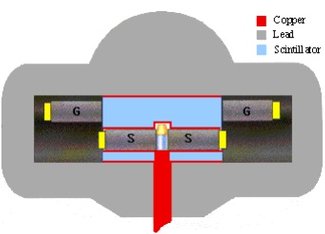
- Passive lead shield around the photomultiplier and the scintillation sample in order to shield away external radiation.
- Active anticoincidence shield around the photomultiplier and the scintillation sample inside the lead shield. This normally consists of a liquid scintillator with its own PM-tubes. This detector is coupled in anti-coincidence to the main detector. The effect is that any event detected in both detectors simultaneously is discarded as a background event and will not be recorded as a true count. This active shield removes background from both external (for instance cosmic radiation) and internal sources (for instance from content of 40K in the scintillation glass).
- Cooling the electronics to reduce electronic noise
- Careful sample preparation
- Using scintillation liquids with low content of 3H and 14C
- Using scintillation vials with low content of natural radioactivity (14C, 40K)
Figure 1: Shielded counting geometry of a modern low-background LSC counting system
Chemiluminescence
Chemiluminescence is the spurious generation of light emissions as a result of chemical reactions between additives or specimens and the components of liquid scintillation. These photon emissions are a result of chemical energy converted into molecular excitation energy, which in turn undergoes decay with the emission of light detected by the PMTs. The amount of luminescence is related to the weight and type of sample used and the properties of the components.
Dioxane-based scintillators and bleaching agents are particularly susceptible to producing chemiluminescence.
To reduce the effects of this phenomenon, samples can be heated gently to 50-60 oC. Letting it rest for some time will also let the luminescence decay.
Photoluminescence
Photoluminescence is simply the emission of photons from an excited molecular species. This may occur in vial walls, caps, and other material activated by light- these emissions may be long-lived. The difference between the two interfering processes is that unlike chemiluminesence, the photoluminescent substance can be repeatedly photo-reactivated by light exposure. Many proteinaceous compounds when dissolved in alkaline solubilizers, particularly hyamine, are subject to photoluminescence after exposure to sunlight or fluorecent lighting.
Photoluminescence can be reduced by acidification of the solventsample, but is best eliminated by dark-adaptation of samples several hours before counting.
Bioluminescence
Bioluminescence is the emission of light due to biochemical processes in the sample. This interference can be reduced by sterilization of the sample and the scintillation cocktail before mixing and counting.
Quenching
Quenching is a phenomenon which results in a reduction of the scintillation count rate. There are three main types of quenching, all of which serve to disrupt the normal chain of events in scintillation counting:
Chemical quenching:
This is caused by materials in the cocktail, which interfere with the process of energy transfer from beta particle to solvent molecule to primary scintillant. Mechanisms include:
- Acid quenching resulting from interaction of H+ with primary or secondary scintillant.
- Excessive concentration of one component which can not take part in the energy transfer process.
- Dilution quenching – dilution increases average distance between solvent molecules.
- Dipole-dipole quenching resulting in loss of energy or increase in vibrational energy which eventually is converted into heat instead of light
- Electron capture preventing the energy transfer from the beta particle to the solvent molecule.
Heavy chemical quenchers are for instance oxo-compounds and halogenated compounds.
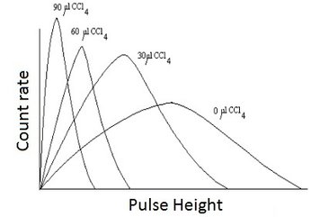
Figure 2: Effect of quenching on energy spectrum with the chemical quencher CCl4.
Color quenching:
A colored material in the cocktail may absorb light photons emitted by the scintillant. This reduces the number of photons emitted from the sample. In practice, all materials have an absorption spectrum. The most serious quenching is in the brown-yellow-red part of the spectrum. Color quenching may be reduced by bleaching or decolorizing, e.g. blood samples have been bleached by peroxide. However, surplus peroxide has to be removed because this will in turn lead to chemical quenching and chemiluminescence.
Physical quenching:
This a common name on all processes, except that of color quenching, that reduce or prevent the light emitted from the scintillants to reach the photomultipliers. This can be unintended particles in the mixture, fingerprints on the scintillation glass, precipitates due to reactions or, in case of counting directly on dispersed solids, the solids themselves.
The effect of the quench processes is that the number of photons reaching the PM-tubes is lower. Hence, one measures a lower energy than original. The peak in the spectrum shifts towards the lower energy region as illustrated in Fig.2.
To solve this problem, methods have been developed, each having benefits and disadvantages. Two methods will be discussed: The Internal Standards Method and the Sample Channels Ratio Method.
Quench correction Methods
Internal Standards Method: The internal standards method is perhaps the most accurate method of quench correction. This method assumes that an added standard of the same radionuclide as is present in the sample will be quenched in a fashion and in amount similar to that of the unknown sample.
The correction method is as follows: Let the radionuclide standard have an activity concentration Ac,st (Bq/g):
eqn 1
where Dst = the disintegration rate and
mst = the mass of the standard solution.
Prepare a scintillation mixture by mixing the liquid scintillator cocktail with a known amount mx of the sample. Count the mixture and let the recorded counting rate be Rx:
eqn 2
where Dx = the unknown disintegration rate in the sample before mixing and
εx = the unknown counting efficiency of the sample mixture.
Add a known amount mst,x of activity (Dst,x) of the standard to the sample mixture and count again. Let the recorded counting rate now be Rx+s:
eqn 3
combining this with eqn: 1 and 2 gives:
eqn 4
This may be solved with respect to εx:
eqn 5
Inserting this onto eqn 2 to fin:
eqn 6
From the known mass mx one may find the activity concentration Ac,x of the unknown sample:
eqn 7
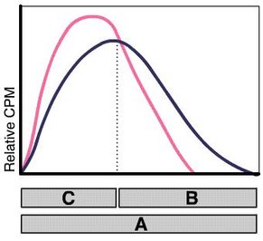
Sample-Channels Ratio Method: The sample-channels ratio method uses two channels for sample counting, and is based on the fact that the pulse height of a beta emitter is always displaced toward lower energy levels when quenching occurs. Counts are lost from the upper to the lower channel( see Fig.2 and Fig.3) .
Figure 3: Unquenched and quenched β-spectrum with the defined counting channels A (whole spectrum), B (upper part)
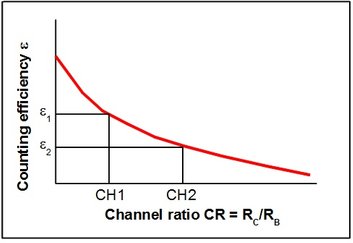
A quench curve is recorded before sample measurment by counting of a series of consecutively stronger quenched samples containing the same activity. The channel ratio CR, for instance RC/RB, changes with the degree of quench. A relation is found between the channel ratio and the counting efficiency. An analytical function:
eqn 8
may be fitted to the experimental points and provide a tool for correct interpolation between the experimental points.
Figure 4: Quench-curve for the channel-ratio quench correction method
Analysis of a sample with unknown concentration of the radionuclide of interest is then performed according to the following procedure:
- Suppose the quench-correction curve is known.
- Count the sample and record the count rates in the two channels B and C:
eqn 9
3. Establish the channel ratio:
eqn 10
4. Put this value into Eqn.8 and calculate εx.
5. Disintegraion rate Dx is then found from eqn.2.
6. From the known weight mx (or volume Vx) of the original liquid sample mixture, activity concentration Ac,x may be fund from Eqn.7.


